Start with the foundation of the ship. Shell Plating Shell Plating consists of Side shell plating Bottom shell plating refers to Horizontal plating from keel to turn of bilge Horizontal plating from keel to turn of bilge is made up of Keel Strake Thickness at different locations due to different loading resulting stresses Strakes types Keel Strake Shell Plating provides the ship Longitudinal strength Shell Plating can be.

Shell Expansion Plan
Draw a reference line in the X direction.

. Make sure that this is a straight line and is parallel to the center line of the ship. Main shell expansion basis drawings with hull boundary lines knuckle lines deck and platform lines stringers and main cutouts such as thrusters and perhaps box coolersea chests. This is a ships plan giving details of Shell plating.
Click Shell Expansion in the Operation toolbar. It is a two dimensional drawing of a three dimensional surface of the ships hull form. Expansion of the character.
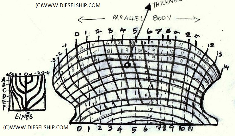
Interpretation of a Shell Plating Expansion Drawing Attached is a portion of the shell plating drawing for an 85 Army ST Tug. Shell expansion The arrangement of the shell plating taken from the 3-dimensional model may be represented on a 2-dimensional drawing referred to as a shell expansion. In the Shell Plates box select a shell plate.
In this video we will show you how to make fast and simple shell expansions from 2D to 3D and backWant to know more. Shell expansion sketch for TM purposes. Start with the foundation of the ship.
BThe shell expansion can be used for finding areas of painting surfaces such as topside boot topping and bottom areas by applying Simpsons rules directly. Shell expansion drawings are girth expansions in the transverse direction of the hull plate system. How to Draw a Sailing Ship.
It is developed from the ships line plan with the contour lines erected straight on the base line representing the ships length. It is a two dimensional drawing of a three dimensional surface of the ships hull form. Add the mast of the sailing vessel.
How Bash expands variables to their values. We will study all the principle aspects of General Arrangement Plan its uses and the correct procedure to readout this drawing. A shell expansion drawing may be created from any workshop design.
Click the Shell Expansion drawing button to display the Shell Expansion dialog. Using the output of a command as an argument. Expansion is performed on the command line after it has been split into token s.
In the Reference box select a reference line. Full port and starboard expansions. All vertical dimensions in this drawing are taken around the girth of the vessel rather than their being a direct vertical projection.
I Shell expansion drawing 111 Lines plan ii Docking plan iv GA drawings of decks. The Shell Expansion dialog box appears. There are seven kinds of expansion performed.
This is a ships plan giving details of Shell plating. It is my understanding that a shell plating diagram shows the stations as a series of verticals and the height or width depending on orientation of the plating at each station is its girth at that station resulting in a pattern that would. Detailed shell expansion drawings with all information from above and additional provide all details necessary for workshop drawing such.
A drawing showing the shell plating of a ship and giving the size shape and weight of the plates and their connections. I Shell expansion drawing 111 Lines plan ii Docking plan iv GA drawings of decks. The hull plate system is created with the Imported Plate System Command in the Molded Forms task.
It is developed from the ships line plan with the contour lines erected straight on the base line representing the ships length. This will be useful exams and for knowing ship construction. Two types of shell expansion are available.
List of Finished Plans onboard or the Index of all Plans onboard you will learn about how to read this index and locate the available plans and drawings. A plan showing the seams and butts thickness and associated welding of all plates comprising the shell plating framing etc. We develop shell expansion drawings of two types.
In effect it determines the position of the expanded plate. Open the structure system and draw a reference line in the X direction. Full port and starboard expansions.
Shell expansion The arrangement of the shell plating taken from the 3-dimensional model may be represented on a 2-dimensional drawing referred to as a. What is Ship Shell Expansion Plan. Click Shell Expansion in the Operation toolbar.
Shell expansion drawings are girth expansions in the transverse direction of the hull plate system. See Create a shell expansion drawing. In the shell expansion the vertical scale used is different from the horizontal scale and a suitable adjustment has to be made when calculating areasThis becomes useful in solving disputes concerning.
Ships Plans and Drawings. Draw the ships deck. The drawing shows the various plate strakes and their identification.
This line is the curve from which the expansion parameters are computed. The reference line should be a straight line parallel to the center line of the ship. Shell Expansion Shell expansion is a two-dimensional drawing showing the arrangement of the shell plates stiffening members all butts seams fillets welds etc.
Shell design expansion is important part to build a vessel shell expansion is two dimensional drawing which is expandable to create a shell being two. In the existing situation because there is no standardization of data it is recorded manually on ship drawings or. E Which of the following drawings is not necessary to undertake ship underwater hull survey.
To avoid complications the bow and aft part are not drawn. Definition of shell expansion. In a short shell expansion plan means plan showing the seams and butts.
Expansion of expressions within braces. The Assignment is to prepare the shell expansion of any ship on a drawing sheet. The drawing shows the girth measurement around the platespositions of all parts plate edges stringers frames and decks from a specified datum position usually but not always the baseline Shell Expansion.
This video will help you understand about shell expansion plan.
How To Draw A Shell Expansion Plan Boat Design Net

Shell And Deck Plating Captain Damley

Fig 17 Shell Expansion Plan The Mold Loft Is Where The Flickr
Shell Expanssion Rhino For Windows Mcneel Forum
Shell Expansion Sketch For Tm Purposes Download Scientific Diagram

Development Of Shell Expansion Drawings Modeca Ltd Ship Engineering Naval Architect
Various Ship Plans Required For Dry Docking

Ship Drawing Offices And Loftwork Ship Construction
0 comments
Post a Comment